Ultra-Cut Auto-Cut Power Supply Low Voltage Bias Supply
作者: 本站 来源: 本站 时间:2016年04月27日
Ultra-Cut / Auto-Cut Power Supply Low Voltage Bias Supply
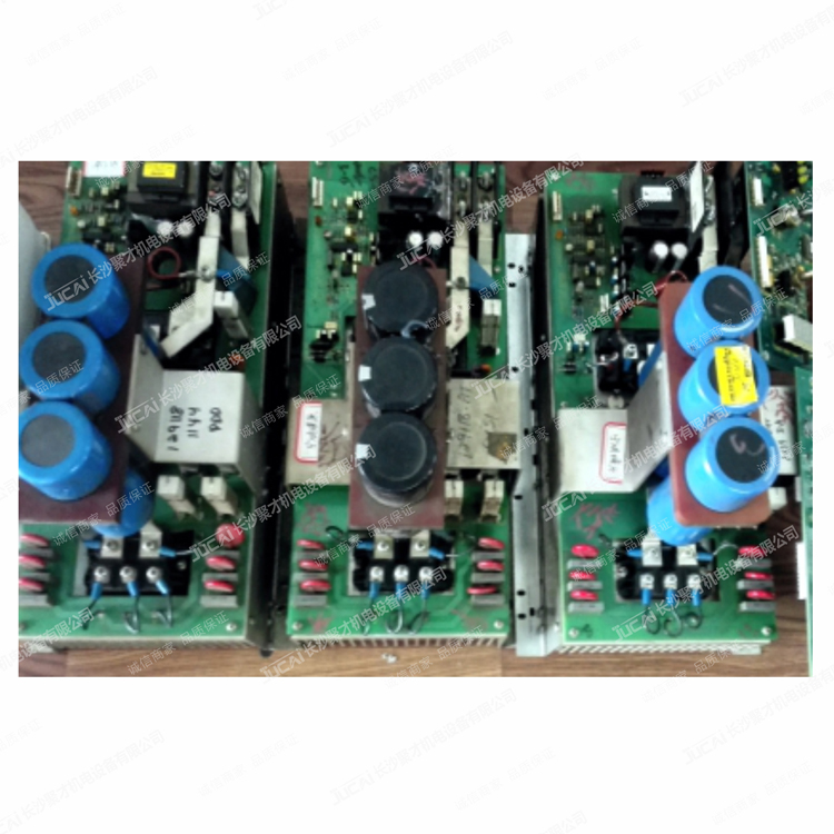
Three phase input voltage passes through the front panel On / Off circuit breaker CP1 and two phases connect to D1, a single phase diode bridge mounted on the upper chassis. Rectified DC from D1 approximately 300-350 VDC for 208-230 VAC input or 600-650 VDC for 400-600 VAC input units, connects to PCB3 on CN1-1 (+) and CN1-5 (-). PCB3 contains an isolated output switching power supply that takes the high voltage DC, and produces +/- 15 VDC and +5 VDC to PCB5. There are also +12 and +5 VDC supplies which are primary referenced, not isolated, for PCB4. There is also a separate, not referenced to common, Also supplies +24 VDC for one Coolant fan (100A & 150/200A supplies).
+/- 15 VDC & +5 VDC for PCB5.
CN32-1 (+15 VDC), CN32-2 (+5VDC), CN32-3 (common or GND), and CN32-4 (-15 VDC) come from CN32 on PCB3 and goes to CN32 on PCB5. There are no test points on PCB3, so if need to measure these voltages on PCB3 you have to get them from the connector pins. Be very careful not to short the meter probes together as this can destroy the PCB. There are test points for these voltages on PCB5. They are TP0 (common or gnd), TP1 (+5 VDC), TP2 (+15 VDC) & TP3 (-15 VDC).
Primary referenced +12 & +5 VDC for PCB4
PCB4 is a daughter board that plugs into PCB3. The connector called CN4 on PCB3 mates with connector called CN1 on PCB4. +12 VDC is on pin 1, +5 VDC on pin 3 and common for both is pin 5. This common, called PGND is not the same as the common for the +/- 15 & 5 V. PGND is referenced to the units primary input power. Be especially careful measuring these voltages.
24 VDC for Fan on 100-200A units.
A separate 24 VDC supply, not referenced to either GND or PGND, comes from CN18-1, +24 VDC also called FAN+, and goes to rear panel circuit breaker CP8 then to TB1 on PCB7 (Relay PCB). 24VGND, also called FAN-, comes from CN18-3 and goes to TB2 on PCB7. A relay RY4, on PCB7, indirectly controlled from the CCM, connects FAN+ to CN5-1 and FAN- to CN5-2 which goes to the fan.
24 VDC for Fans on 300A units.
The 24 VAC on PCB3 has enough power for one fan which is used in 100, 150 & 200A units. 300A unit has two fans so has a separate power supply called DSC1 for its fans. The 100 VAC secondary of T1 is connected to CN1-1 & 3 on the DCS1 power supply PCB. DSC1’s output comes from CN3-5 (FAN+) and CN5-4 (FAN-) and goes to TB1 & 2 on PCB7. A relay RY4, on PCB7, indirectly controlled from the CCM, connects FAN+ to CN5-1 & 3 and CN5-and FAN- to CN5-2 & 4 which goes to the two fans.